
Mitering for Reduced Triangle Counts
Mitering is a brushwork technique that aligns and trims intersecting faces so the compiler does not introduce unnecessary vertices and splits. It requires a small amount of extra setup time, but consistently yields lower triangle counts in-game and cleaner lightmap data.
Original vs. Optimized Design
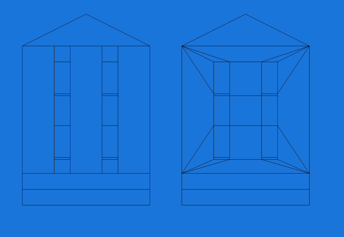
Left: original wall for quick iteration.
Right: mitered wall optimized for triangle counts.
The optimized version uses more editor brushes, but their placement controls how the compiler subdivides faces, preventing needless splits at intersections. This gives you predictable, efficient geometry once compiled.
In‑Game Comparison
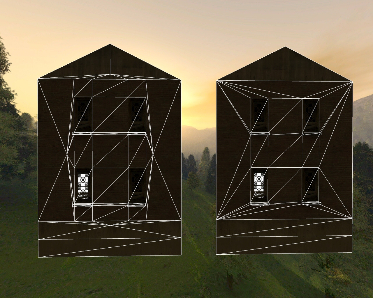
Left: additional vertices appear where brush vertices meet other brush edges, inflating triangle counts.
Right: mitered geometry avoids those extra splits; only quads are split once into two triangles.
In the unoptimized wall, the outermost brushes are each divided into eight triangles due to intersecting vertices and edges. The mitered wall avoids these intersections, minimizing splits.
Measured Results
| Design | Triangles | Reduction |
|---|---|---|
| Unoptimized | 71 | |
| Optimized (mitered) | 47 | ≈ 40% |
Scaling effect. Saving 28 triangles per wall across four walls is 112 triangles per building. Reusing that building (or variations) ten times yields about 1,120 triangles saved in the scene. Across large maps, similar optimizations accumulate to thousands of triangles removed.
Why It Helps
- Fewer draw calls per surface. Avoiding accidental vertex-edge intersections reduces compiler-introduced splits.
- Cleaner lightmaps. Larger, more regular triangles produce more stable lightmap UVs and fewer seams.
- Predictable geometry. Intentional brush alignment gives you control over final triangle flow and where BSP brush splits occur.
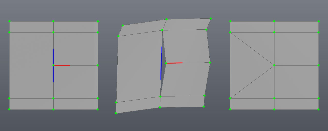
Mitering Reduces T-Junction issues
A T-junction (or T-junc) is a small crack between the edges of polygons where a vertex intersects an edge often (but not always) in the form of a letter "T". This often causes a visual artifact commonly referred to as "sparklies", which look like small flickering pixels along an edge. Q3Map2 does try to solve for T-juncs, but doing so automatically will often results in a high number of generated polygons. A little manual brush slicing allows you to solve both problems.
Below is an actual example, a collection of polygons with vertexes highlighted in green. On the left, the red line highlights an edge that intersects another edge highlighted in blue. It may look okay right now, but what you can't see is the tiny fracture between the polygons. The tiny fracture is what causes the "sparklies" effect. This becomes apparent (center) when we stretch the polygons and you can see a hole appears between the polygons where the red edge meets the blue edge. This is because the vertex at the end of the red edge does not have an accompanying vertex on the blue edge to weld with. The problem can be solved by splitting the polygons so that the blue edge has an extra vertex point to weld with the red edge as seen on the right.
Most of the time, Q3Map2 will automatically split surfaces to create additional vertexes for welding. It doesn't always do this intelligently, it basically traces a cut to the nearest vertex or sometimes places a new vertex right in the middle of a polygon. A little manual polygon management with the clipper tool goes a long way to solve these cases.
Another issue has to do with patch mesh curves, they cannot be split by Q3Map2 to solve for T-junc errors, so you have to pay special attention to where the major control points of patches meet with other patches and brushes.